In circuit design, the power supply is often overlooked, but it plays a crucial role in the overall performance and cost of the system. One aspect of power supply design that is frequently neglected is the use of capacitors in DC-DC converter design.
Capacitors are primarily used in power supply design for filtering and decoupling/bypass purposes. Filtering involves removing specific frequency bands from signals to suppress and prevent interference. It is based on probability theory and methods of estimating related random processes. The term “filtering” originated from communication theory, where it refers to extracting useful signals from received signals that contain interference. In the context of power supply design, “received signals” can be seen as observed random processes, while “useful signals” can be regarded as estimated random processes.
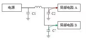
Filtering mainly aims to eliminate external noise, while decoupling/bypass (one method of achieving decoupling effects is by using bypass capacitors) aims to reduce the interference caused by external noise on local circuits. These two concepts are often confused. To clarify, let’s consider a circuit structure:

The capacity of the filter capacitor can often be calculated from the data sheet of the power chip. If the filter circuit uses electrolytic capacitors, tantalum capacitors and ceramic capacitors at the same time, place the electrolytic capacitors closest to the switching power supply to protect the tantalum capacitors. The ceramic capacitors are placed behind the tantalum capacitors. In this way, th In the given figure, a DC-DC converter supplies power to circuits A and B. The current passes through capacitor C1 and then splits into two paths through PCB traces to supply A and B respectively. When circuit A requires a high current momentarily, without capacitors C2 and C3, the voltage at the A terminal would drop due to the inductance of the line. Moreover, the voltage at the B terminal would be affected by the changes in the A terminal voltage. This means that the current fluctuations in circuit A can impact the power supply voltage of circuit B, leading to interference in the B circuit’s signals. Similarly, current changes in circuit B can also interfere with circuit A, resulting in “co-channel coupling interference.”
Also Read: All About DC-DC Converter for Drone Charging
By adding capacitor C2, when the local circuit (A) requires a momentary high current, C2 can temporarily provide the necessary current for A. Even if line inductance exists in the common circuit section, the voltage at the A terminal will not drop significantly. Consequently, the impact on circuit B will be greatly reduced. Therefore, decoupling is achieved through the bypassing of current using capacitors.
In general, larger capacitors are primarily used for filtering purposes, where the speed requirement is not very fast, but the capacitance value is relatively large. If the partial circuit A in the figure refers to an individual chip, it is advisable to place the capacitor as close as possible to the power pin of the chip. However, if “partial circuit A” represents a functional module, ceramic capacitors can be utilized. In case the capacity of the ceramic capacitors is insufficient, tantalum capacitors or aluminum electrolytic capacitors can also be used. It is important to ensure that each chip in the functional module has its own decoupling capacitor, preferably a ceramic capacitor.
The decoupling capacitor, an essential component, must fulfill two criteria: capacity and equivalent series resistance (ESR). This implies that a single 0.1uF capacitor may not provide as effective decoupling as two 0.01uF capacitors. Additionally, 0.01uF capacitors exhibit lower impedance at higher frequencies. If a 0.01uF capacitor can satisfy the capacity requirements at these frequencies, it will deliver superior decoupling capabilities compared to 0.1uF capacitors.
Many high-speed chip design guidelines with many pins will give the power design requirements for decoupling capacitors. For example, a BGA package with more than 500 pins requires at least 30 ceramic capacitors for a 3.3V power supply, and several large capacitors, with a total capacity of more than 200uF.
As a basic component, capacitors play an important role in electronic circuits. In traditional applications, capacitors are mainly used for bypass coupling, power filtering, DC blocking, and oscillation and delay in small signals. With the development of electronic circuits, especially power electronic circuits, different special requirements are put forward for capacitors in different applications.
Let’s delve into the structure of a capacitor. At its simplest form, a capacitor consists of two plates situated at opposite ends with an insulating dielectric material (which can include air) in between [1]. When charged, the plates accumulate a voltage, also known as a potential difference. However, due to the presence of the insulating material, the capacitor remains non-conductive. It is important to note that this condition holds as long as the voltage across the capacitor does not surpass its critical voltage, commonly referred to as the breakdown voltage. It is worth mentioning that all substances possess inherent insulation properties, but when the voltage surpasses a certain threshold, the substance can undergo electrical conduction. This critical voltage is termed the breakdown voltage.
Capacitors are no exception. After the capacitor is broken down, it is no longer an insulator. However, in the middle school stage, such voltage is not seen in the circuit, so they all work below the breakdown voltage and can be regarded as an insulator. However, in an AC circuit, the direction of the current changes as a function of time. The process of charging and discharging the capacitor has time. At this time, a changing electric field is formed between the plates, and this electric field is also a function of changing with time.
Leave a Reply